

Taper Bushes vs Locking Assemblies: Choosing a Keyless Joint
How taper bushes and keyless locking assemblies carry torque, where each one fits, and which bore and hub checks decide whether the joint holds.
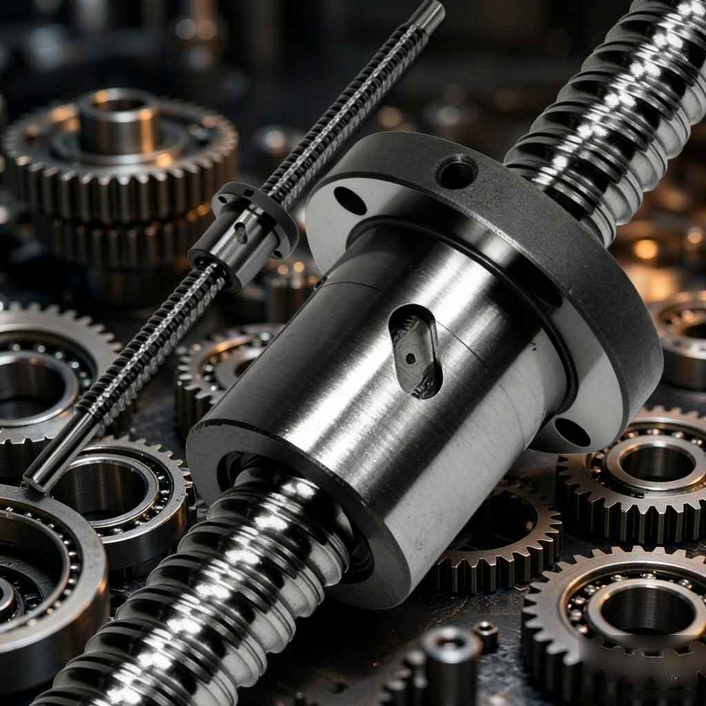
Most gearboxes are still assembled around keyways, and for good reason: a keyway is easy to specify, easy to cut, and easy to inspect. It is also a stress riser cut into both members, it removes section exactly where a shaft is already working hard, and it leaves clearance that has to be crossed every time the load reverses. Two alternatives avoid the key entirely, and they are routinely confused with each other on the shop floor.
Two components, two different fits
A taper bush is a split sleeve with a taper on its outside. The hub must be machined with a matching tapered bore. The bush is pressed in from one side, two or three screws draw it axially, the taper closes, the bore contracts, and the assembly grips the shaft. Removal is done with the same screws moved into jacking holes, which push the bush back out.
A locking assembly — also sold as a keyless bushing or power lock — is not part of the hub. It is a set of rings that fits between a plain bore and a plain shaft, with mating tapers between the inner and outer elements. Tightening the screws drives the rings along those tapers so both expand radially and press on shaft and bore at the same time. Nothing in the hub has to be tapered.
That single difference decides which one a drawing can accept. If the hub already exists with a straight bore, a locking assembly is the only option without re-machining. If the hub is being made for the application, a taper bush is cheaper to buy and quicker to replace.
Where the torque actually comes from
Both designs transmit torque through friction generated by radial contact pressure. Datasheet figures therefore depend on surface finish, fit, lubrication and screw torque, not on the shear strength of a key. RINGFEDER specifies its RfN 7012 locking assembly for shafts at k9 to h9 and hubs at N9 to H9, with k11 to h11 and N11 to H11 acceptable at the loose end, and a surface finish of Ra 3.2 µm or better on both contact surfaces. The screws are grade 12.9, and the catalogue allows tightening torque to be reduced to half the stated value, in which case torque capacity, axial force and surface pressure all fall roughly in proportion.
That last relationship is worth reading in reverse. More screw torque is not the same as more margin. Over-tightening is how thin-walled cast iron hubs get split; under-tightening is how a joint creeps, polishes the taper to a bright ring, and starts to walk under load. A torque wrench and a written figure do more for reliability here than a larger size.
The two families also differ in what happens during tightening. A symmetrical double-taper design holds shaft and hub in position relative to each other while the screws come up, which matters when the gear has to sit at a defined axial position. Single-taper designs draw the hub along the shaft as they are tightened, so axial position has to be set after clamping or allowed for in the layout.
Reading a taper bush table
Take a 2517 bush from a published range. It is 44.5 mm long, 85.5 mm across the large end, and uses two 1/2 inch BSW screws at 50 N·m. Without a key it carries 380 N·m on a 38 mm bore and 510 N·m on a 48 mm bore. Minimum hub diameter is 130 mm in cast iron at 180 N/mm², and 108 mm in steel at 600 N/mm². In the same range, a 1008 bush on a 12 mm bore carries 29 N·m, while a 5050 on a 125 mm bore carries 7370 N·m.
The spread between those two ends is the point. Selection is a two-sided calculation: the bore sets the size, the torque sets whether that size is enough, and the hub diameter sets whether the hub can take the surface pressure that size produces. Fit a key as well and the slip plane moves from the shaft-bush interface out to the bush-hub interface, raising capacity roughly in proportion to the ratio of large-end diameter to bore.
Taking the key out, and putting it back
Frequent dismantling and phase adjustment are the clearest reasons to go keyless. A gear on a servo shaft has a defined angular relationship to an encoder zero; with a key, every re-assembly means finding that relationship again, while a clamped joint releases and re-clamps without moving it.
Small shaft diameters are the second reason. A keyway removes section and adds two sharp corners on a part that has little material to spare. Reversing duty with a backlash requirement is the third: a key moves through its clearance on every reversal, and a friction joint has no gap to cross. Space is the fourth — locking assemblies can be stacked, and several units within a distance of 4·L add their torque ratings, which suits a narrow hub carrying a large moment.
A key is still the better answer in some conditions. Heavy shock loads, rapid reversals, and sites where nobody owns a torque wrench all favour the keyed joint, because the clamped joint is only as good as its assembly procedure. Thin cast iron hubs are limited by surface pressure, and once the next size up will not fit, the friction route runs out of room. Cost matters too when volumes are low and the hub is already being keyed for other reasons.
What the drawing has to say
Keyless joints remove the assembly stage’s ability to absorb error. A keyed joint hides a little eccentricity in key clearance; a clamped joint centres hard, so whatever runout exists in the parts turns directly into mesh error. In a keyless design, concentricity between gear bore and tooth tips is a drawing requirement, not an assembly problem to be solved later.
For the hub, four features carry the joint: taper angle and contact pattern, checked with marking compound and read across the full face; bore tolerance and roundness, which decide how clamping pressure is distributed; face runout, which becomes the datum wherever the assembly seats against a shoulder; and keyway-to-bore symmetry on parts that mix both connection types. On the gear, grinding the bore before grinding the teeth — locating on the finished bore — is what keeps runout low after mounting. Reverse that order and the part comes back.
PinyiGear machines gears, sprockets, timing pulleys and matching hubs to drawing: modules M0.5 to M20, production accuracy DIN 4 to 5 with ground gears to DIN 3; materials including 20CrMnTi, 20CrMo, 20CrNiMo, 42CrMo, 40Cr, 38CrMoAl and 45#; hobbing, shaping, milling and grinding combined with carburising, nitriding, induction hardening and quenching-and-tempering, plus CNC turning and milling and internal and external grinding; inspection on a gear measuring centre, CMM, roundness tester, hardness tester, roughness tester and mesh check. For spur gears machined to this standard, see the spur gear range; drawings and duty conditions go to www.dgpinyi.com.