

Rack Drives on CNC Machine Tools and Laser Cutters
Why rack pitch error, joint alignment and mounting faces decide accuracy on long CNC and laser axes, and where ground, milled and hardened rack fit.
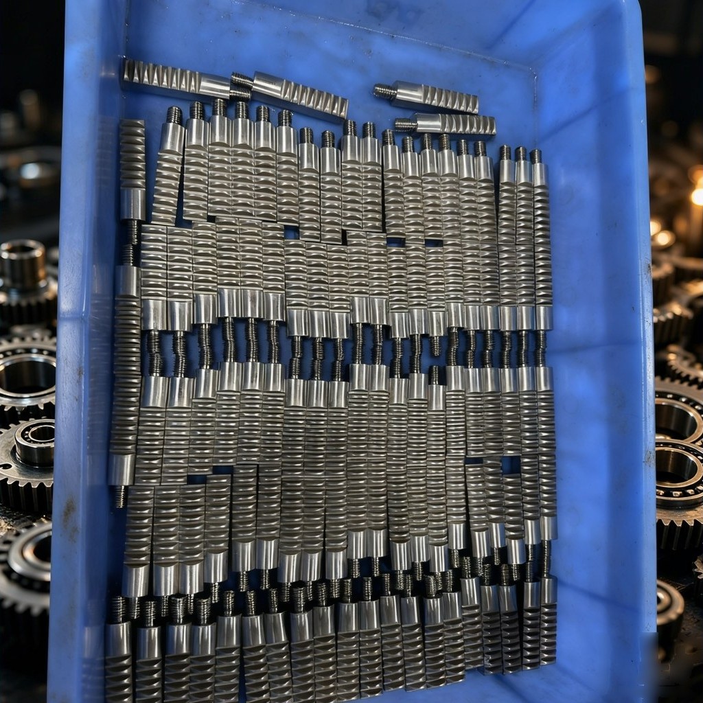
A ball screw is a fine answer until the axis gets long. Past two or three metres of travel, critical speed, shaft sag and thermal growth all start crowding the design, and a rack and pinion begins to look like the quieter option: servo rotation becomes linear motion, and the stroke runs as far as you are willing to bolt sections together.
What you pay for that is a longer accuracy chain. Four things decide where the tool or the laser head actually lands — the rack’s own cumulative pitch error, the fit at each joint, how the mounting faces sit on the bed, and what the tooth flank does under load and wear. Let any one of them go, and the coordinate drifts.
One number matters more than the grade on the label
DIN designations such as 6h25, 8e27 and 10e27 describe tolerance bands. For a rack, the figure worth carrying into a design review is cumulative pitch error referred to a length. Ground rack, helical or straight, holds DIN 6h25 at 0.036 mm per 1000 mm. Straight milled rack in the quenched and tempered condition sits at DIN 8e27 and 0.08 mm per 1000 mm. The induction-hardened milled version is DIN 10e27 at 0.13 mm.
On a short machine, the gap between those three numbers may never surface in a finished part. On a six-metre laser gantry it will, because error accumulates across every section you add instead of averaging itself away. So the useful opening question about a rack is not the grade. It is the travel length, and only then the grade.
Joints are where long axes fail
Standard lengths are 500 mm and 1000 mm, which means a long axis is a series of joints. A technical article published by gear-racks.com on 25 August 2026 separates joint failure into three mechanisms: pitch-line offset, where the two sections sit at different heights relative to the mounting datum; angular misalignment, where adjacent tooth faces are not collinear and the pinion meets a kink on every pass; and cumulative pitch error, where the tooth spacing of one section fails to continue the pattern set by the previous one. The article puts a figure on the sensitivity — a step or gap of 0.05 mm is enough for a pinion tooth to strike the edge of a tooth space rather than roll into it, generating shock loads that grow with speed.
0.05 mm sits in the same order of magnitude as the 0.036 mm per 1000 mm a ground rack is specified to. Those two facts belong side by side in a specification review, because they carry one message: a joint done badly cancels most of the accuracy you paid for.
There is another way to deal with it — sort the error out rather than grind it out. Linear Motion Tips has described a scheme in which each rack carries a 2D code encoding its measured pitch error; before assembly the sections are scanned and ordered so that the errors offset one another along the whole axis. The idea is not exotic. What it requires is traceable measurement data on every single piece, which is a different thing from a certificate stating that the batch passed.
Stiffness is not just hardness
Hardening to HRC 48–52 handles flank wear, pitting and plastic flow. It does nothing about a rack that will not sit flat on the bed. Four-face grinding is the step that tends to get skipped in cost discussions and it is the one that matters here: the ground faces are the mounting datum, so contact area and the distortion left after the bolts are torqued become predictable rather than incidental. S45C covers most machine tool work; SCM440 comes in where load and shock run heavier.
The tempered option deserves a paragraph of its own, because it is often misread as a downgrade. Milled rack at HRC 18–20 and DIN 8e27 is the right call when the part still has to be drilled, slotted or tapped after mounting. Harden the part before those operations and they become a problem. Asking whether secondary machining is needed, before the grade is fixed, saves a rework loop later.
Straight or helical
Laser cutters spend much of their shift in rapid traverse, and helical teeth suit that: greater contact ratio, more continuous meshing, lower noise and less impact per tooth. The cost is thrust. A helical rack pushes axially, so bearings, clamps and guideways have to be sized for that component. The helix on our racks is right-hand 19°31'42" at a 20° pressure angle. Straight teeth carry no axial load and suit slower, heavier-cutting machines — stiff structure, shorter travel, deep cuts.
Either way, pinion and rack must share module, pressure angle, helix angle and hand. That belongs on the drawing, not in an email thread.
Inspection belongs to the whole axis
A linear axis is a rack, a mating pinion, often a spline shaft and a bearing housing. Splines are cut to GB/T 3478 or DIN 5480, with shaft diameter tolerance commonly held at h6/h7. Acceptance should include profile, lead and base tangent data from a gear measuring centre or a CMM, plus hardness and surface roughness records. A label reading “conforming” tells you nothing about which link failed on the day the axis started marking parts.
One note from the industry
Gear Technology’s State of the Gear Industry 2026, by Aaron Fagan in the January/February issue, reports on a survey of 137 respondents. Klingelnberg is quoted saying that the strongest pull for bevel gear equipment, cylindrical gear grinding machines and high-end metrology “continues to originate in Asia” — China, India, Japan and Korea — a pattern that has held for five years. The same feature describes how machine tool builders now treat automation-friendly configuration, automatic closed-loop correction and connectivity as requirements rather than options. (Source: Gear Technology, State of the Gear Industry 2026)
Machines moving toward closed-loop correction and higher throughput place a tighter demand on the rack inside them, not a looser one.
What PinyiGear makes
PinyiGear covers gears from module M0.5 to M20, with production running at DIN 4–5 and ground teeth reaching DIN 3. Racks are split into a ground line and a precision-milled line, module 1 to 12, standard lengths of 500 mm and 1000 mm, joined to suit the stroke. Materials include 20CrMnTi, 42CrMo, 40Cr and 45# selected against duty. Inspection runs through a gear measuring centre, CMM, roundness and hardness testers, roughness measurement and a mesh check. Drawings and duty data can go to the contact details on www.dgpinyi.com.