

Key and Keyway Fit: Tolerances, Torque and the Shaft
How key section, keyway fit class and dimensioning decide whether a keyed joint carries its rated torque, and where the shaft loses margin instead.
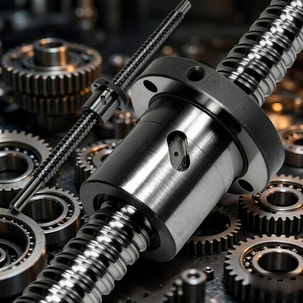
A gear decides whether a shaft turns accurately. The key decides whether the torque arrives intact. The two flanks of the key bear against the walls of the keyway, and torque crosses the joint as bearing pressure. The clearance between them is not a question of how the assembly feels in the hand: it fixes where the load sits on the key and how much area carries it.
The section comes from the shaft
DIN 6885-1 and ISO 773 size a parallel key from the shaft diameter rather than from torque, because keyway depth is limited by what the shaft section can spare. The bands covering most reducer and gearmotor work:
| Shaft diameter (mm) | Key b × h (mm) | t1 in shaft (mm) | t2 in hub (mm) |
|---|---|---|---|
| over 22 to 30 | 8 × 7 | 4.0 | 3.3 |
| over 30 to 38 | 10 × 8 | 5.0 | 3.3 |
| over 44 to 50 | 14 × 9 | 5.5 | 3.8 |
| over 50 to 58 | 16 × 10 | 6.0 | 4.3 |
Diameter is a starting point, not a verdict. A hollow shaft, a light drive or a thin hub wall can justify a smaller section once bearing pressure is checked; a reversed drive usually wants a longer key rather than a taller one.
Three fit classes, three duties
Key width is h9 in every case. What varies is the tolerance zone on the two keyways, and that choice is a statement about how the joint will be serviced.
- Normal — N9 in the shaft, JS9 in the hub. Fixed hub, dismantled occasionally. JS9 is symmetrical about nominal, so the hub goes on either way round.
- Tight — P9 in both. Alternating torque, shock load, or a joint where play is not acceptable. It has to be pressed, and once pressed and pulled it will not hold again.
- Free — H9 in the shaft, D10 in the hub. The hub slides along the shaft, as on a clutch collar.
A reducer output under reversing duty and a fan shaft turning one way at steady load should not share a fit, even at the same diameter and the same key section.
Dimension it so an inspector can measure it
Keyway depth t1 is awkward to verify: a caliper cannot reach from the slot bottom to the opposite side of the shaft, and a depth micrometer referenced to the slot edge measures something else.
Working drawings call out d − t1 instead, so the inspector measures from the slot bottom to the far generator of the shaft. The number is then reproducible with an outside micrometer. In the hub, d + t2 does the same job. This is not drafting taste; it decides which instrument is used and whether two inspectors return the same value on the same part.
Torque capacity is checked twice
Key capacity is normally checked on two failure modes, and the shorter answer governs.
- Shear across the key: τ = 2T / (d · b · L)
- Bearing pressure on the flank: σ = 4T / (d · h · L)
T is torque, d shaft diameter, b key width, h key height, L the effective length in contact. Keys are commonly cut from medium-carbon steel, and IS 2048 requires key steel with tensile strength not below 600 MPa.
The value substituted into those formulas is the allowable stress from the design handbook, chosen against material and duty, not the tensile strength of the bar. Treating tensile strength as allowable stress is how a joint that calculates comfortably fails in the field.
What the keyway does to the shaft
This is the half of the calculation that gets skipped.
Cutting the slot reduces the effective section from d to d − t1, and torsional capacity runs with the cube of diameter. Take a 40 mm shaft with a 12 × 8 key: t1 is 5 mm, so the section at the slot is 35 mm, and 35³ against 40³ leaves about two thirds of the torsional capacity — a one-eighth loss of material, a one-third loss of strength, before any stress concentration is counted.
The slot bottom is a stress raiser on its own. Locate it on a journal that is already small, or next to the root circle of a gear, and that concentration stacks on the bending stress the tooth root carries. Failures of this type start on the line between the two features, and the key looks fine in the failure report because the key was never the weak link.
Sequence decides whether the fit survives
Keyways are milled, shaped or broached before heat treatment as a rule: the slot is easier to cut soft and the tool lasts longer. After carburizing and quenching, slot width and symmetry move — noticeably on a case-hardened shaft, and unevenly when the keyway breaks the section on one side only.
Two routes are honest. Leave stock and finish the slot after hardening by grinding or broaching: holds the band, costs a hard-machining operation, and needs allowance reserved on the drawing. Or accept the as-quenched width and widen the band, which is cheaper and fine for many general drives provided the fit class is picked for the wider band rather than the nominal one.
Both work. The drawing has to name one. Left to the shop floor, the choice is made by whoever is on the machine that shift, and the next lot may come out different.
What we hold in production
Keyways at PinyiGear are cut by slotter, broach and CNC milling with position held to 0.01 mm. Symmetry and parallelism are checked with a keyway gauge and a CMM, because a key bearing on one flank only is usually a symmetry or parallelism problem rather than a size problem. Shaft surfaces are turned and ground on the same datum scheme as the bearing seats, so keyway, gear seat and journals share one axis instead of three.
Gears and shaft-type drive parts are cut to drawing from module M0.5 to M20, with production accuracy at DIN 4–5 and ground teeth reaching DIN 3. Materials include 20CrMnTi, 20CrMo, 20CrNiMo, 42CrMo, 40Cr, 38CrMoAl and 45#, with carburizing, nitriding, induction hardening or quench-and-temper chosen against duty. Inspection runs through a gear measuring centre, CMM, roundness and hardness testers, roughness measurement and a mesh check.
Where the industry is moving
At IMTS 2026 the push from gear machine builders was toward tool condition and process stability rather than another decimal on a spec sheet. One builder gave a robotic camera system its public debut, using machine vision with artificial intelligence to inspect cutting tool condition, alongside a form grinder taking gears to 260 mm outside diameter and a power skiving machine covering internal and external teeth to 300 mm diameter, 100 mm face width and 5,000 rpm spindle speed (Source: Gear Solutions, September 2026, https://gearsolutions.com/news/nidec-machine-tool-america-touts-advanced-gear-manufacturing).
For a keyway the implication is direct. A drifting tool shows up in the non-tooth features before anyone measures a tooth flank, and buyers running their own inspection cells now ask for width, d − t1, symmetry and parallelism as numbers rather than a conformance label.
Six lines decide the life of a keyed joint: width with its tolerance zone, d − t1 in the shaft, d + t2 in the hub, slot length, the datum the slot is referenced to, and the process sequence around heat treatment. Send the drawing to our contact page and we will check the shaft section before quoting.
Related reading: precision shafts, splines and gear shafts.