

Choosing Between Soft and Hard Gear Tooth Flanks: How the 350 HBW Threshold Drives Material, Heat Treatment and Process Routing
The 350 HBW line separates soft from hard gear tooth flanks: below it, 45 steel at 217-255 HBW and 40Cr at 241-286 HBW are quenched and tempered; above it, 20CrMnTi is carburized to 58-62 HRC case with 30-45 HRC core.
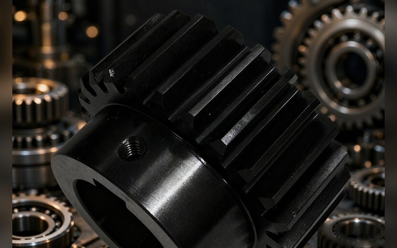
The design decision behind it
The choice between a soft tooth flank and a hard one is not a material preference. It is a decision about where you want the accuracy to be created, and when.
On a soft flank — hardness stays below roughly 350 HBW after quench and temper — the teeth are cut before heat treatment. The hob or shaper produces the final tooth form, and the thermal step follows. Distortion exists, but it acts on a form that was already finished, and for many applications the resulting deviation is tolerable. The route is short: cut, treat, inspect. Cost stays moderate because there is no grinding operation after hardening.
On a hard flank — surface above roughly 45 HRC, typically through carburizing — the order reverses. Heat treatment comes first, then tooth grinding restores the form and the accuracy. This is not a matter of preference either: once the surface reaches 58–62 HRC, cutting tools no longer remove material economically, so grinding becomes the only way to hold tooth geometry. The reward is a gear that carries the same load in a smaller envelope, or carries more load in the same envelope.
So the practical question at the design stage is not “which is better” but “what am I optimizing”. If the housing has room, the load is steady, and the budget is tight, a quenched-and-tempered flank is usually the rational answer. If the package is fixed, the speed is high, or impact is present, the extra grinding step buys you something real. The 350 HBW line is an industry convention for describing this split; no standard defines it as a threshold, and the number should be treated as a shorthand for two different process routes rather than a physical law.
One more consideration belongs in the decision: impact. Carburizing leaves residual compressive stress in the surface layer, and the core stays tough at 30–45 HRC. That combination tolerates shock loading better than a through-hardened part of comparable surface hardness. Where the gear sees reversing loads or intermittent peaks, this matters more than the hardness number alone.
Numbers that matter on the drawing
A gear drawing communicates through a small set of numbers, and each one has a measurement convention attached. Getting the convention wrong is as damaging as getting the value wrong.
| Item | What to state | How it is normally verified |
|---|---|---|
| Material grade | Steel designation, e.g. 45, 40Cr, 42CrMo, 20CrMnTi | Mill certificate, incoming inspection |
| Heat treatment method | Quench and temper / surface quench / carburize and quench | Process record, hardness survey |
| Flank hardness | Range with unit — HBW or HRC, not both mixed | Hardness tester on tooth flank or test piece |
| Core hardness (carburized) | Separate range from surface | Sectioned coupon or test bar |
| Effective case depth | Value in mm, with the defining hardness criterion | Microhardness traverse on coupon |
| Accuracy grade | Standard cited as the basis of marking, e.g. ISO 1328 or DIN 3962 | Involute and lead measurement |
| Grinding allowance | Per-side value in mm, where grinding follows hardening | Checked at pre-grind stage |
Two conventions deserve emphasis. First, hardness units are not interchangeable across processes — a quenched-and-tempered flank is quoted in HBW, a carburized surface in HRC, and writing “hardness 55” without a unit invites a wrong route. Second, accuracy grade must be tied to a standard by name. Citing ISO 1328 or DIN 3962 tells the shop which measurement system and which tolerance tables apply; it does not by itself fix a grade, so the grade number has to appear alongside.
For carburized parts, effective case depth is the number most often left vague. It is defined against a hardness criterion and measured on a coupon that sees the same cycle as the production parts. A drawing that names a depth without naming the criterion is ambiguous, and two suppliers can read it two ways.
Where custom manufacturing changes the answer
When gears are made to a drawing rather than selected from a catalogue, the parameters that drive cost are not the ones buyers usually watch. Module and tooth count are visible and easy to compare; the cost is decided elsewhere.
Grinding allowance and case depth interact. A carburized gear needs enough stock to grind away distortion without grinding through the hardened layer. Specify too little allowance and the grinder has no room; specify too much and either the case depth must grow or the finished surface risks falling below the specified hardness. The two numbers have to be set together, and both scale with module.
Tooth geometry decides tooling access. Narrow face widths, small root fillets, shoulders close to the tooth ends, and undercut conditions all affect whether a standard cutter reaches the root. A design that is fine on paper can require a special cutter or an extra operation. This is a geometry question, not a hardness question, and it applies equally to soft and hard flanks.
Blank design sets the heat-treatment risk. Asymmetric webs, abrupt section changes, and thin rims distort more during quenching. Where the drawing permits, a more symmetric blank reduces the correction the grinder has to make — and sometimes reduces the grinding allowance needed.
Tolerance stack-up across features. A gear with tight bore tolerance, tight face runout, and tight tooth accuracy concentrates all the difficulty in one setup. Each requirement is achievable; their combination determines how many operations and how much fixturing the job needs. Reviewers look at the stack, not the individual callouts.
Quantity changes the route, not the geometry. For a small trial batch, a carburize-and-grind cycle carries a long route relative to the number of parts. Where the load allows, a quenched-and-tempered flank reaches the same function with fewer steps. The drawing should leave room for that conversation rather than locking a single route before the process review.
Common mistakes in drawings and enquiries
Steel grade given, heat treatment omitted. The same 40Cr can be quenched and tempered or surface quenched, and the resulting flank hardness differs by nearly a factor of two. The shop cannot quote a route it cannot see. Fix: state grade, treatment method, and hardness range as three separate entries.
Hardness written without a unit or scale. “HB 250–280” on a part intended for carburizing is a contradiction, and a supplier may quote the wrong process or query the drawing late. Fix: match the unit to the process — HBW for soft flanks, HRC for hardened surfaces — and give surface and core values separately where both apply.
Carburized parts with no grinding allowance or no case depth. Distortion during quenching is unavoidable, and tooth grinding is what recovers accuracy. Without a stated allowance, the grinder may cut into the case; without a case depth and its criterion, the heat treater has no target. Fix: specify per-side allowance and effective case depth with the defining hardness criterion.
Accuracy grade cited without a standard, or a standard without a grade. “Grade 6” alone leaves the measurement system open; “ISO 1328” alone leaves the tolerance band open. Fix: name the standard and the grade together, and state which deviations — total, pitch, profile, lead — are controlled.
Enquiry with a 3D model but no material, treatment, or duty description. Geometry alone does not determine route or cost, and the reply becomes a range wide enough to be useless. Fix: attach the 2D drawing with the material column complete, plus speed, load character, and whether impact is present.
A short checklist
Print this and run it against the drawing before it goes out.
- Steel grade stated, and consistent with the intended heat treatment
- Heat treatment method named (quench and temper / surface quench / carburize and quench)
- Flank hardness given as a range with the correct unit and scale
- Core hardness stated separately for carburized parts
- Effective case depth stated, with the hardness criterion that defines it
- Grinding allowance given per side where grinding follows hardening
- Accuracy grade and the standard it is marked against both present
- Controlled deviations identified (total, pitch, profile, lead)
- Blank geometry reviewed for section symmetry and distortion risk
- Duty description attached: speed, load character, impact, envelope limits
FAQ
Is 350 HBW a value written into any standard?
No. It is an industry convention used to separate soft-flank from hard-flank practice, not a figure defined by a standard. What a drawing should carry is the actual hardness range and the treatment method, so the route is unambiguous.
Can a soft-flank gear and a hard-flank gear share the same drawing?
Only if the drawing leaves the treatment open, which usually creates more questions than it answers. The two routes differ in operation sequence, grinding allowance, and inspection method, so the drawing should commit to one route or explicitly state that alternatives are acceptable for review.
Why does a carburized gear need a grinding allowance on the drawing?
Because quenching distorts the part, and tooth grinding after hardening is what restores the tooth form and accuracy. The allowance tells the shop how much stock to leave; it has to be set together with case depth so the hardened layer is not ground through.
Send your drawing — with the material column complete and the duty conditions noted — to sales@dgpinyi.com or call +86 18002857601, and our engineering team will review it and come back with process and quotation feedback.