

Worm Gears and Worms for High-Ratio Drives
Worms and worm wheels to the drawing — ZA, ZN, ZI and ZK profiles, bronze wheels, carburised and ground steel worms, pairs checked on a meshing tester before shipment.
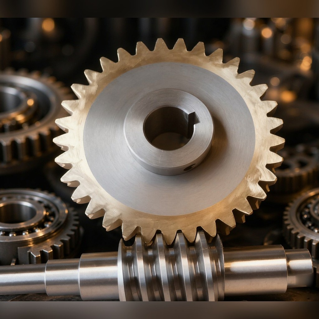
A worm pair does two things at once: it takes a large reduction in a small envelope, and — depending on the lead angle — it refuses to run backwards. Reducers, rotary tables, hoists and conveyors all use the same geometry for those two reasons, but the balance between them changes with the number of starts.
PinyiGear machines worms and worm wheels to the drawing: profiles ZA, ZN, ZI and ZK, bronze wheels, carburised and ground steel worms, supplied as matched pairs with the contact patch checked before dispatch.
What a worm pair buys, and what it costs
Shafts meet at 90°, so input and output face different directions and the housing can be compact. Ratio per stage runs far higher than a spur pair of the same size — up to 80:1 in the range we build — which often removes a reduction stage entirely.
The price is efficiency. A single-start worm passes roughly 60–70% of input power through to the wheel; the rest becomes heat in the mesh and has to leave through the housing. More starts improve that materially — three starts reach about 80–85%, four to six 85–92% — but the ability to hold position disappears as the lead angle opens up.
| Starts | Efficiency (approximate) | Self-locking |
|---|---|---|
| 1 | 60–70% | Locks with a small enough lead angle |
| 2 | 70–80% | Depends on friction — locking possible |
| 3 | 80–85% | No |
| 4–6 | 85–92% | No |
Those figures are approximations and shift with flank roughness, lubrication and assembly alignment. Where self-locking is part of the design premise, it has to be confirmed against the actual lead angle and friction coefficient rather than assumed from the table — a worm specified as self-locking that slips under vibration is a safety problem, not a performance shortfall.
Profiles: ZA, ZN, ZI, ZK
The profile decides the tooling, the grinding method and how the part is measured.
| Profile | Form | Where it fits |
|---|---|---|
| ZA (Archimedes) | Straight axial section | Turning and measuring are straightforward; general duty |
| ZN (normal straight) | Straight in the normal section | Suited to grinding |
| ZI (involute) | Straight form on the base-cylinder tangent plane | Holds accuracy after grinding; higher precision work |
| ZK (conical enveloping) | Generated by the grinding wheel | Batch grinding with consistent results |
Once the profile is fixed, the wheel form, the grinding method and the measurement plan follow from it. A drawing that does not name a profile leaves the shop to pick one, and two shops will pick differently.
Working ranges
Worm
| Accuracy | Module | Starts | Material |
|---|---|---|---|
| GB 7–8 | M1–M12 | 1–6 | 20CrMnTi, 42CrMo |
| GB 7–9 | M1–M10 | 1–4 | 40Cr |
Worm wheel, by mating material
| Ratio | Module | Teeth | Material | Matching worm starts |
|---|---|---|---|---|
| 7.5:1 to 80:1 | M1–M12 | 30–80 | ZCuSn10P1 tin bronze | 1–6 |
| 10:1 to 60:1 | M1–M10 | 30–60 | ZCuAl10Fe3 aluminium bronze | 1–4 |
| 10:1 to 50:1 | M1–M8 | 30–50 | QT500-7 ductile iron | 1–4 |
Tin bronze is the default for loaded drives because it tolerates sliding contact and conforms to the worm under load. Aluminium bronze carries more load at lower speed but is harder to run in. Ductile iron suits light duty where cost dominates.
Process route
Worm. Carburising and quenching of 20CrMnTi brings the flank to HRC 58–62 — a hard case over a tough core, which is the combination that resists both wear and tooth breakage. For lighter duty, 40Cr quenched and tempered or induction hardened gives HRC 48–55 at the surface.
Grinding. Quenching distorts the flank, so rough grinding restores geometry and finish grinding brings it to class. Ground worms hold GB 6–7, one grade tighter than milled, and the difference shows up as lower noise and less heat in the mesh.
Wheel. Tin bronze wheels are hobbed from M1 to M12 with a purpose-made hob. Contact between worm and wheel is a line, not a point, so a small centre-distance error moves the contact zone and concentrates wear. Tooth thickness and centre distance are therefore both controlled, not just the tooth profile.
Pair verification. Worm and wheel are made and shipped as a pair. Contact patch position and area are checked set by set, then re-checked on a meshing tester.
Accuracy
| Class | Operation | Range |
|---|---|---|
| GB 7–8 | Worm milling | M1–M12 |
| GB 6–7 | Worm grinding | M1–M10 |
| GB 7–8 | Wheel hobbing | M1–M12 |
| GB 8–9 | Wheel fly cutting | M1–M8 |
Supporting operations: CNC turning to 0.005 mm, cylindrical and face grinding to 0.001 mm.
Inspection and documentation
Each shipment carries inspection reports with pitch deviation, profile deviation, helix deviation and tooth surface hardness. Those numbers are what let a customer decide whether a noise found at installation belongs to the gear or to the assembly — without them, both sides guess.
Measuring equipment on the route: gear measuring centre, CMM, hardness tester, roughness tester.
Where worm drives are used
- Industrial speed reducers — the most common application; ratio and centre distance come from the housing drawing
- Indexing and rotary tables — pitch error becomes angular error directly, so the accuracy class has to be derived from the indexing tolerance, not chosen by habit
- Conveying and lifting machinery — a single-start worm holds a stopped load without a brake
- Crossed-axis drives in tight envelopes — where a bevel pair will not fit
- Custom transmission units — built to drawing after a machinability review
What to send
- Worm and wheel drawings (PDF, DWG, DXF, STEP), or module, starts, tooth count and ratio
- Centre distance, and the housing drawing if the pair has to fit an existing case
- Accuracy class, or the indexing or positioning tolerance the drive has to hold
- Duty: torque, speed, duty cycle, ambient and lubrication method
- Whether self-locking is a requirement, and what load it must hold
- Quantity and whether the order is a prototype, a first batch or repeat production
An engineer reviews the drawing first and responds with the process route, a wheel material recommendation and the inspection plan before a price is fixed.
Send a worm gear drawing for quotation
FAQ
How do I know whether the pair will self-lock? It depends on the lead angle and the friction coefficient in service, not on the number of starts alone. Single-start with a small lead angle is the usual route; confirm it against the actual duty, because vibration and lubrication change the answer.
Tin bronze or aluminium bronze? Tin bronze for loaded, higher-speed duty and where running-in matters. Aluminium bronze where load is high and speed low, or where the environment rules out tin bronze. Ductile iron only for light duty.
Can you match an existing housing? Yes — the centre distance and mounting are taken from the housing drawing. That is usually the fixed constraint, and the gear geometry is built around it.
Why does a worm drive run hot? Because the sliding contact in the mesh converts the efficiency loss into heat. At 60–70% efficiency a single-start pair generates a third of input power as heat, which has to leave through the housing or a cooler.
Do you supply the pair or individual parts? Pairs. Contact patch and backlash are properties of the set, so shipping a worm alone gives a part that measures correctly and may still run badly against an existing wheel.