

Gear Racks Machined to Customer Drawing
Straight and helical gear racks cut and ground to your drawing — module 1 to 12, DIN 6 to 10 classes, joined sections for long travel, inspection report per batch.
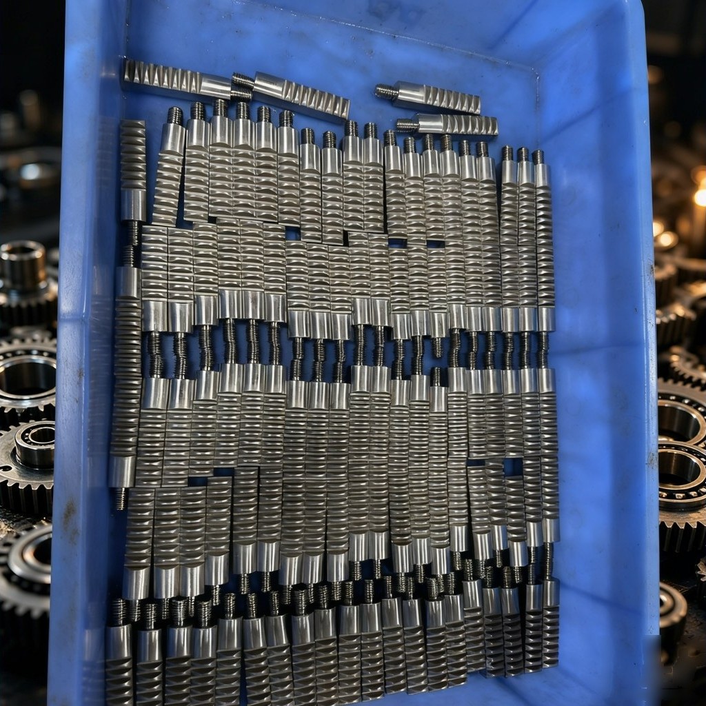
A gear rack turns rotation into travel. The pinion does the turning, the rack does the travelling, and everything that goes wrong on a long axis — pitch accumulating, a joint that catches, a tooth that wears into a step — arrives as position error at the tool or at the laser head.
PinyiGear cuts and grinds racks to the drawing rather than to a stock catalogue. Module, pressure angle, helix angle, bar length, joint positions, material, heat treatment and accuracy class all come from the print. This page covers what belongs on a rack drawing, how the tooth is machined and measured, and which decisions actually decide whether a long axis still holds its tolerance after two years in service.
What a rack drawing has to define
Most incomplete rack drawings are missing one of three groups of information. All three drive the price, so all three belong on the print.
Tooth geometry. Module or diametral pitch, pressure angle, helix angle if the rack is helical, tooth height, face width, and the profile itself. If the rack replaces an existing part the profile may be non-standard, which is workable — but it has to be dimensioned, not described.
Length and joints. Bar length, how many sections make up the axis, where the joints fall, and how the ends are machined. A 2 m axis built from 1 m bars has one joint; a 6 m axis has five, and each one is a place where the accuracy can be lost.
Material, heat treatment and accuracy class. Steel grade, surface hardness where specified, and the class the finished tooth is measured against. Without a named class, “accurate” means whatever the supplier decides it means.
A drawing carrying those three groups can be quoted directly. One that does not usually produces a round of questions before anything can be priced.
Tooth geometry: what each parameter decides
Module sets tooth size and, with it, the load one tooth can carry. PinyiGear works from module 1 to module 12. Small modules suit instrument and light automation axes; large modules appear where the pinion has to push a heavy gantry or a machine table carrying a workpiece.
Pressure angle decides how much of the load runs along the flank and how much pushes radially. The common values are 20° and 14.5°. 20° is the working default for machine tool duty because it carries more load per unit of face width without undercutting at low tooth counts.
Helix angle applies to helical racks. A helix raises the contact ratio — more teeth share the load at any instant — which spreads load, softens the impact per tooth and cuts noise. Our helical racks are cut right-hand at 19°31'42" with a 20° pressure angle, but the drawing governs: if the mating pinion calls for left-hand or a different angle, the rack follows. A helical rack also produces axial thrust, and that thrust has to be absorbed by bearings and guideways, not by the rack.
Face width and tooth height come from the load calculation on the customer’s side. We cut to the drawing instead of proposing a size, because the rack only sees the load the machine design puts through it.
Straight or helical: the trade
| Straight rack | Helical rack | |
|---|---|---|
| Contact ratio | Lower — teeth engage and release with an impact each time | Higher — load transfers gradually across overlapping teeth |
| Noise | Louder at speed | Quieter, which counts on laser and high-speed gantries |
| Axial thrust | None | Present — bearings and clamps must be sized for it |
| Typical use | Slower, heavier cuts; short to medium travel; woodworking and press feeds | Machine tool rapid traverse, laser and plasma gantries, high-speed automation |
The choice usually belongs to the machine designer, not the rack supplier. What matters at our end is that rack and mating pinion share module, pressure angle, helix angle and hand — a mismatch there produces noise and wear that no amount of tooth accuracy can correct.
Material and heat treatment
Material follows duty. The grades we machine most often:
| Grade | Treatment | Resulting hardness | Where it fits |
|---|---|---|---|
| 45# / S45C | Quench and temper, or induction hardening of the tooth | About HRC 18–20 tempered; tooth surface HRC 48–52 induction hardened | General machine frames, medium load, parts needing secondary machining after hardening |
| 40Cr | Quench and temper, optional induction hardening | About HB 260–300 tempered | Medium load, moderate speed, general automation |
| 42CrMo / SCM440 | Quench and temper, optional induction hardening | About HB 280–320 tempered | Heavier load, shock, large section racks |
| 20CrMnTi | Carburising and quenching | Surface HRC 58–62, core HRC 30–42 | High load with sliding contact, long service life |
Two decisions matter more than the grade name.
Whether the part still needs secondary machining after hardening. If the rack has to be drilled, slotted or tapped once it is mounted, milling it in the quenched and tempered condition — and hardening afterwards, or not hardening at all — is often the practical route. Harden first and those operations turn into grinding work.
Whether the mounting faces are ground. Hardening addresses flank wear and pitting. It does nothing for a rack that will not sit flat. Grinding all four faces makes the mounting surfaces the datum, so contact area and the distortion left after bolts are torqued become predictable. This is the step most often dropped from a cost comparison, and it is the one that decides whether a long axis stays straight.
Accuracy class and how the tooth is measured
Rack accuracy is normally stated as a DIN class plus a cumulative pitch error referred to a length. The three levels that come up in practice:
| Class | Cumulative pitch error | Typical process |
|---|---|---|
| DIN 6h25 | 0.036 mm per 1000 mm | Ground, straight or helical |
| DIN 8e27 | 0.08 mm per 1000 mm | Precision milled, quenched and tempered |
| DIN 10e27 | 0.13 mm per 1000 mm | Milled, induction hardened |
Those figures describe the tooth. They do not describe the axis. A 6 m travel built from six 1 m sections accumulates whatever error each joint adds on top of the rack’s own pitch error, so on long travel the joint can matter more than the grade on the drawing.
Joints: where long axes lose accuracy
Sections are commonly supplied in 500 mm and 1000 mm lengths, so any long axis is a chain of joints. Three mechanisms cause trouble:
- Pitch-line offset — the two sections sit at different heights against the mounting datum, so the pinion climbs and drops at every pass.
- Angular misalignment — adjacent tooth faces are not collinear and the pinion meets a kink instead of a continuous flank.
- Cumulative pitch error — the tooth spacing of one section does not continue the pattern of the previous one.
A step or gap around 0.05 mm is enough for a pinion tooth to strike the edge of a tooth space instead of rolling into it, which produces shock loading that grows with speed. That figure sits in the same order as the pitch error of a ground rack, which is why a badly made joint can cancel most of the accuracy the class was meant to deliver.
There are two ways to deal with it. The first is assembly discipline: one datum, matched section heights, tooth alignment checked across every joint before the bolts are finally torqued. The second is error compensation — sections measured individually, then ordered so their errors offset one another along the axis. Compensation needs traceable measurement data on every piece, which is a different thing from a certificate saying the batch passed.
We supply sections with the joint faces machined as datum surfaces and with measured pitch error reported per section, so the assembly team can order them deliberately rather than by chance.
Machining and process route
A rack goes through some or all of these steps, depending on the drawing:
- Blank preparation — sawing, then milling or turning the section to size.
- Stress relief where the section is heavy or the class is tight, so distortion comes out before the teeth are cut.
- Tooth cutting — hobbing or milling the tooth space depending on module and profile; helical racks are cut with the helix angle set on the machine.
- Heat treatment — carburising, induction hardening or quench and temper, per the drawing.
- Grinding — flank grinding for DIN 6 class work, four-face grinding where the mounting surfaces are functional.
- Secondary operations — end machining, mounting holes, locating features, chamfers.
- Marking — section number, orientation mark and joint sequence, so assembly is not guesswork.
The order matters. Grinding the mounting faces after hardening, and cutting holes after stress relief, are the sequencing details that decide whether the finished rack sits flat.
Inspection
Every batch is measured and the report travels with the parts:
- Tooth profile, lead and pitch on a gear measuring centre, measured values compared against the class on the drawing
- Cumulative pitch error reported over the measuring length, not just pass or fail
- Hardness — surface, and core where specified
- Case depth on carburised parts
- Surface roughness on ground flanks
- Geometry — straightness, flatness of the mounting face, section length, on a CMM or surface plate
- Mesh check with the mating pinion where the customer supplies it or orders the pair
A certificate reading “conforming” tells a buyer nothing about which link failed when an axis starts marking parts. Measured values do.
Packing and shipping
Racks are long, thin and easy to bend in transit. Sections are packed with edge protection and, for export, in wooden or plywood cases, with orientation marks preserved so the joint sequence survives the trip. Multi-section orders leave numbered in the order they should be assembled.
Where racks are used
Machine tool axes, laser and waterjet cutting gantries, automation and robot seventh axes, woodworking and panel processing equipment, press feeds, packaging lines, stage and lifting equipment. In most of these the rack works as half of a pair, so an inquiry usually needs two drawings: the rack and the pinion. Backlash and centre distance are settings between two parts, not properties of the rack alone.
What to send with an inquiry
- Rack drawing (PDF, DXF, STEP, DWG or IGES) with tooth geometry, length and joint positions
- Pinion drawing if the pair is ordered together
- Material and heat treatment if they are fixed; if not, state the duty and the grade can be selected
- Accuracy class, or the axis length and the position tolerance the machine has to hold
- Quantity, and whether the order is a prototype, a first batch or repeat production
Send those and the quotation covers the tooth, the mounting faces, the joints and the inspection — not just a price per metre.
Send a rack drawing for quotation
FAQ
Can you cut a rack to a non-standard profile? Yes. The profile comes from the drawing. What we need is a dimensioned profile rather than a description, so the cutter and the inspection plan can be set against it.
Do you supply the pinion as well? Yes, and it is the better way to buy a pair. Backlash and centre distance are set between the two parts, so having both made against the same reference removes one source of mismatch.
How long can a single rack be? Standard sections are 500 mm and 1000 mm. Longer sections are possible depending on module, material and class; beyond that the axis is built from joined sections. The practical limit is set by distortion during heat treatment, not by the machine.
Is induction-hardened rack enough, or does it have to be ground? For many automation and woodworking axes, induction hardened is enough. Where the axis is long, the speed high or the position tolerance tight, the pitch error and joint discipline of a ground rack are what hold the number, and the price difference buys exactly that.
What do you need to quote a joint-matched set? Joint positions, the assembly datum and the accuracy class for the whole axis, not just per section. Error compensation along a long axis only works if the target is defined for the entire travel.